

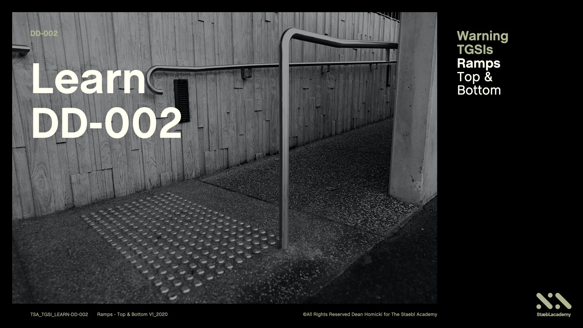
Ramps- Top and Bottom
Course: DD-002 | Length: 3:50 mins | Instructor: Dean Homicki
Chapters
00:23 - Learning Overview
01:34 - Learning Session
01:58 - Let’s Begin
03:13 - Learning Resources
Transcript
This learning session will cover the use of Warning TGSIs on:
Ramps- Top and Bottom
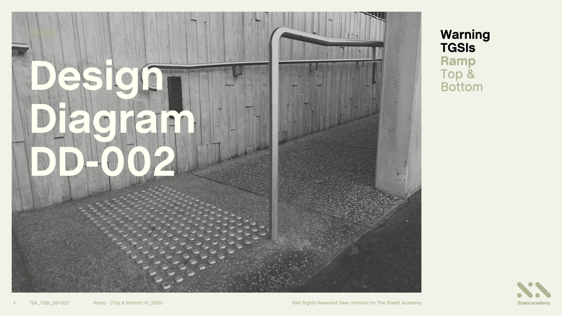
Welcome to staebl.academy TGSI Design Diagram 002. I’m Dean Homicki and I’ll be your guide for this course.
Learning Overview
Let’s review one type of Accessible Ramp together and extract what the Australian TGSI Standard requires of the situation.
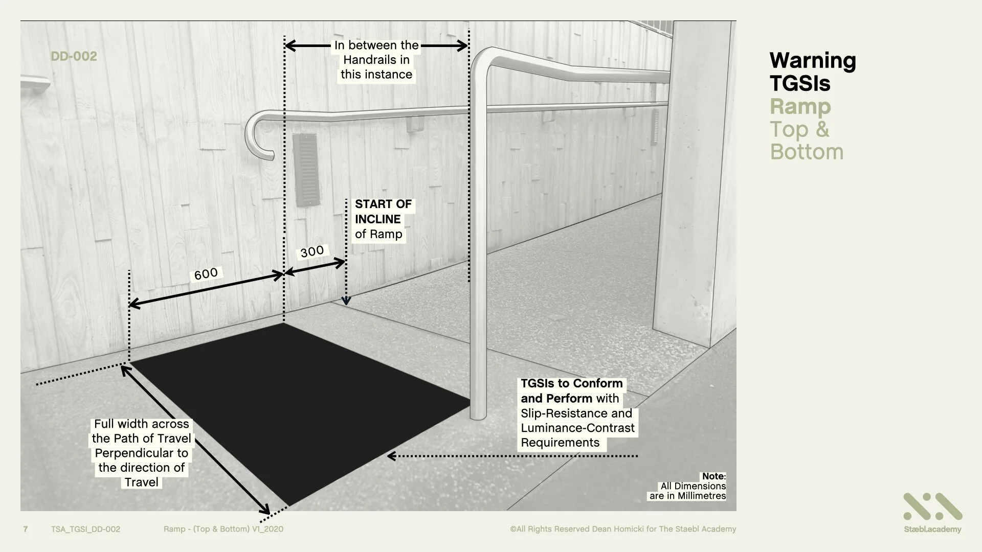
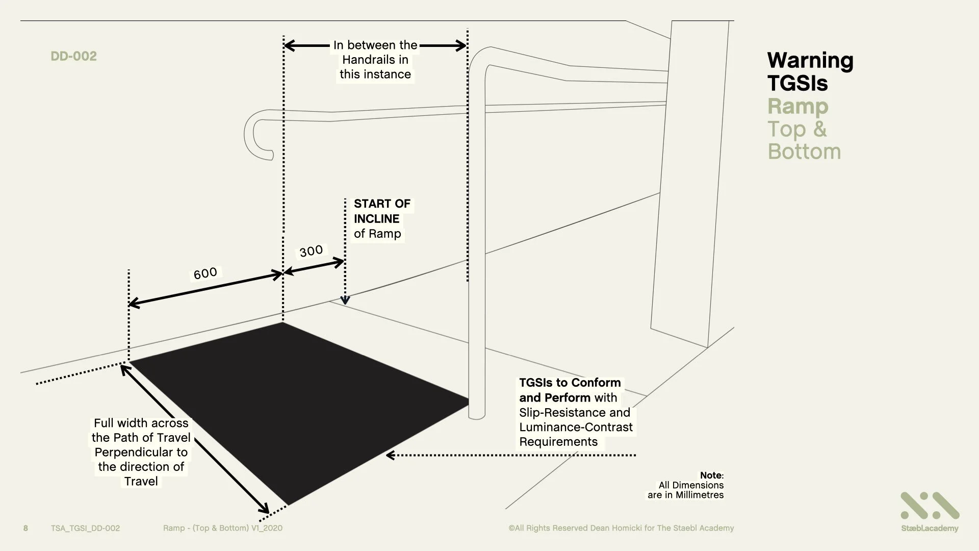
Warning TGSIs Shall be set back 300 mm with a tolerance of +/-10mm from the base of the incline (Bottom), and from the top of the incline (Top), to a minimum depth of 600mm, for the full width across the Path of Travel, and must be perpendicular to the direction of travel.
TGSIs for this application shall also conform and perform, with the applicable Slip-Resistance and Luminance Contrast Requirements.
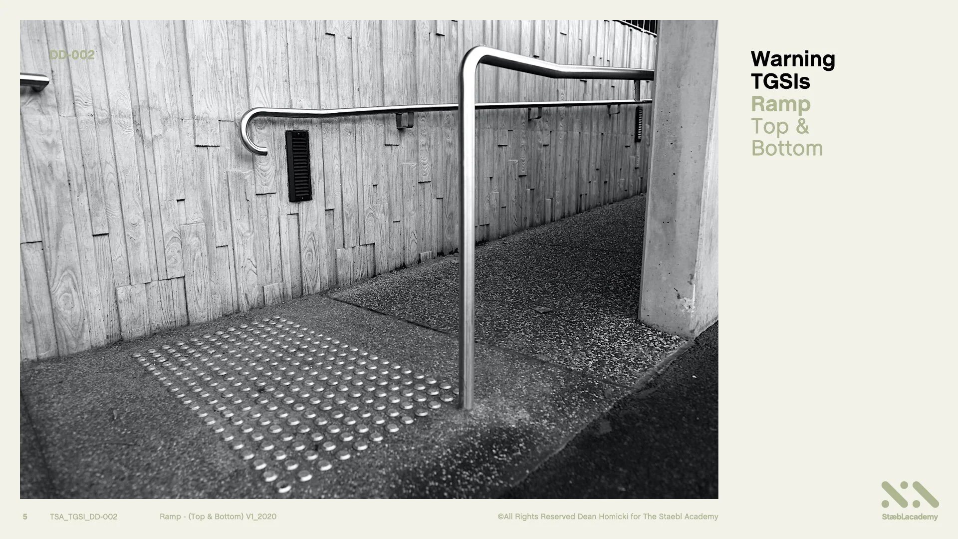
Here is a real-life situation displaying the Base or Bottom of an Accessible Ramp with Discrete Composite Warning TGSIs installed.
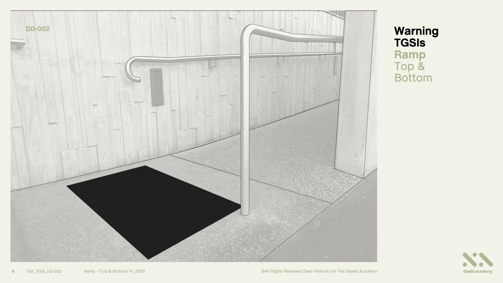
We are going to now convert this image it into a perspective line drawing and view how TGSIs have been used in this application. Here’s the line drawing of the image.
Learning Session
In this example, people can approach this Ramp from various angles. For the orientation of persons who are blind or vision-impaired, applying this knowledge enables us to determine how to use TGSIs and conform to the Normative and Informative Guidelines of the Australian TGSI standards.
Let’s Begin
At the Bottom of the Accessible Ramp, we have an ‘Open Area’ - that is, an area that is accessible at various angles of approach to the hazard. The hazard is this situation is the Ramp Incline. This would apply to the Top of the Ramp as well.
So, from the start of the incline of the Ramp, we require Warning TGSIs to be set back from the start of the incline, 300 mm back with a tolerance of +/- 10 mm for a minimum depth of 600 mm. This equates to 12 TGSI nodes at 50 mm spacings. This equates to 12 TGSI nodes at 50 mm spacings for the full width across the Path of Travel and, must be perpendicular to the direction of travel.
As handrails have been installed on each side of the Accessible Ramp, the TGSIs shall be installed in between the Handrails as this is the accessible path of travel.
TGSIs for this application, also need to conform and perform, with the applicable Slip-Resistance and Luminance-Contrast Requirements.
Warning TGSIs would also need to be installed at the Top of Ramp in the same manner. And here is a real-life TGSI application once again.
Learning Resources
That’s the conclusion for Warning TGSIs Ramp Top and Bottom.
You can also access this course as a concise series of design diagrams in the resource section of our website staebl.academy/design. To access this resource now, click on the link below this video.
Thanks for joining me here at the staebl.academy. I look forward to guiding you through another learning session in the near future. Bye for now.
Listen
Click/Tap the audio player below to listen to the written transcript of this design session as an audible version. This is a streamed broadcast from the Staebl.academy site.
Diagrams
Click/Tap on an image from this learning session to view it as a larger picture. You will then be able to scroll through each individual design diagram in this slide-deck for a closer inspection.


Sources
TSA-TGSI-LEARN-DD-002 - This staebl.academy course module has drawn information from the following sources:
AS/NZS 1428.4.1: 2009 Design for Access and Mobility: Means to assist the orientation of people with a vision impairment - Tactile Ground Surface Indicators - Section 2, 2.1 (b), 2.2 (a) & (b), 2.3.1 General, 2.3.2, 2.3.3 (a), (b), (e), (f) & (g), 2.4 Paragraph 1, Fig 2.3 (B) Drawing (c), Fig 2.1 (a), (b) & (c) AMDT No.2 Dec 2014
AS 1428.1: 2009 General Requirements for Access - New Building Work - 10.3 Ramps (e), (f), (h) & Fig. (16) & (25a), (25b) & (25c)
