

Railway Crossing- Track Crossing with a Pedestrian Maze
Course: DD-010 | Length: 7:47 mins | Instructor: Dean Homicki
Chapters
00:25 - Learning Overview
02:16 - Learning Session
02:29 - Section 1 - Footpath
05:09 - Section 2 - Footpath Shoulders
07:08 - Learning Resources
Transcript
This learning session will cover the use of Warning TGSIs on a:
Railway Crossing- A Track Crossing with a Pedestrian Maze
Welcome to staebl.academy TGSI Design Diagram 010. I’m Dean Homicki and I’ll be your guide for this course.
Learning Overview
Let’s review one type of Railway Crossing, a Track Crossing with a Pedestrian Maze, and together extract what the Australian TGSI Standard, and Part 7 of the Manual of Uniform Traffic Control Devices Standard, and what they both require from a situation such as this.
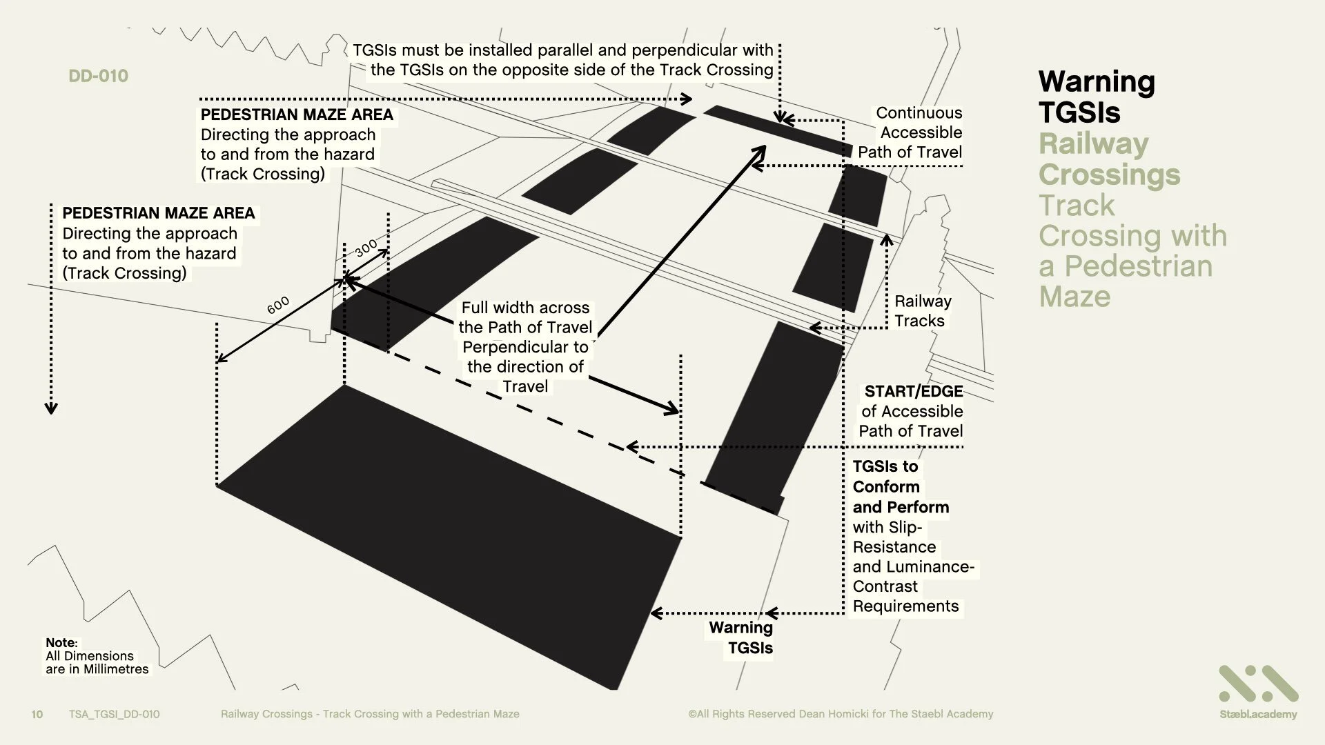
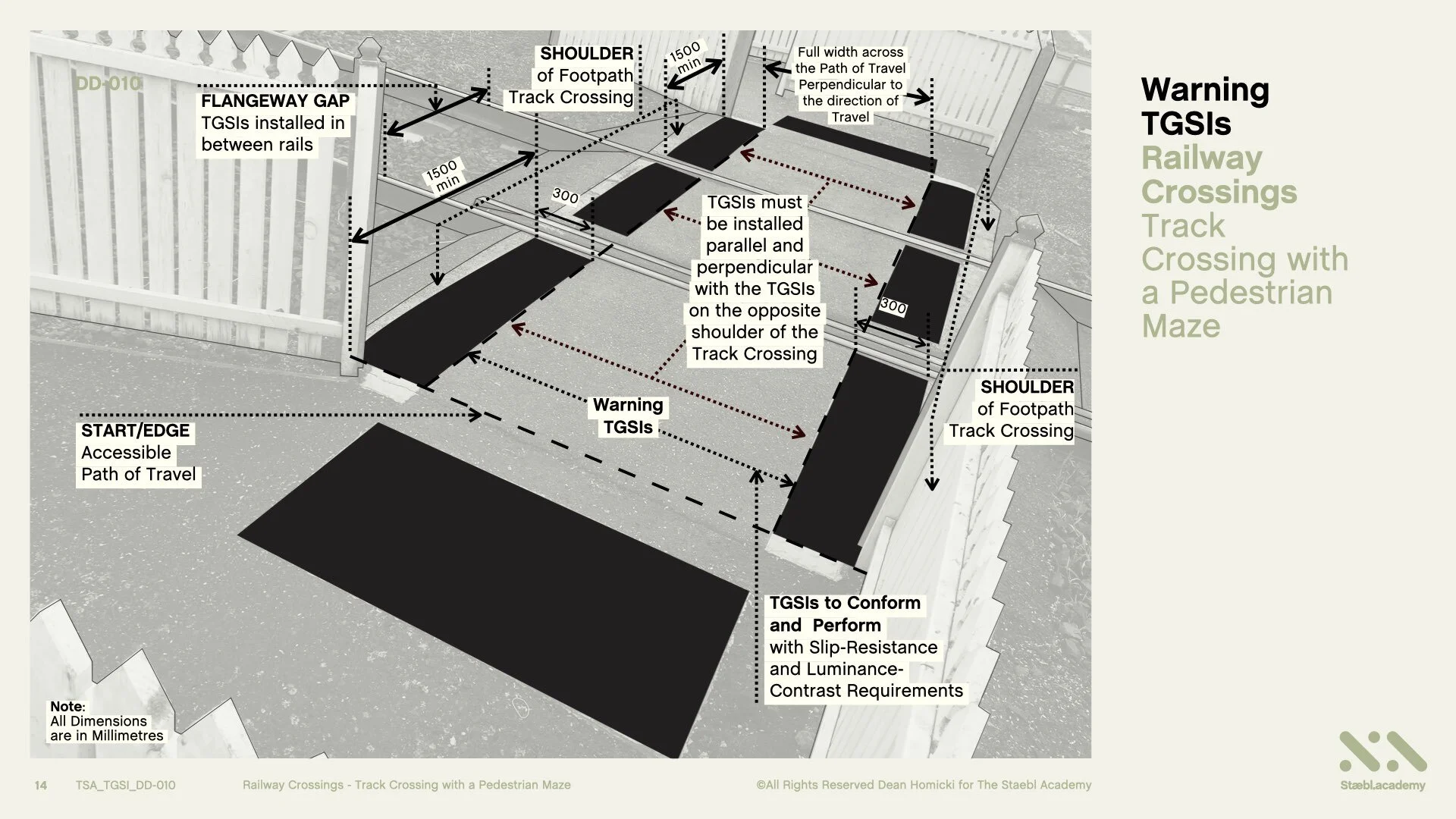
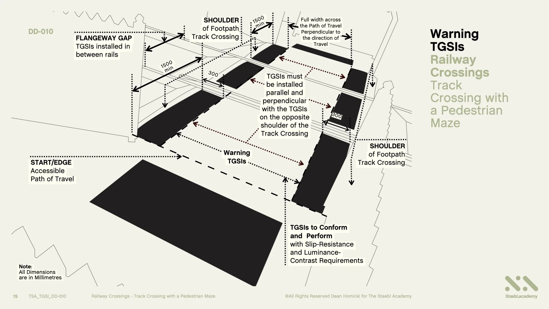
Warning TGSIs Shall be set back 300 mm, with a tolerance of +/- 10 mm, from the Track Crossing Opening inside the Maze, or, from the nearest point of the Enclosure Fence opening to a minimum depth of 600 mm, for the full width across the Path of Travel and, must be perpendicular to the Direction of Travel.
TGSIs must be installed parallel and perpendicular with the TGSIs on the opposite side of the Track Crossing.
TGSIs must also be Installed on Footpath Shoulders on both sides of the Track Crossing. These need to be applied parallel to each other, and from the start of the Maze Track or, (the Maze Track Crossing Opening), and from the nearest point of the Enclosure Fence opening, for the full length of the Footpath.
TGSIs for this application shall also conform and perform, with the applicable Slip Resistance and Luminance Contrast Requirements.
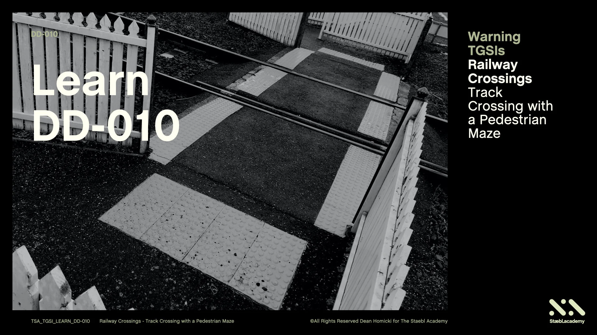
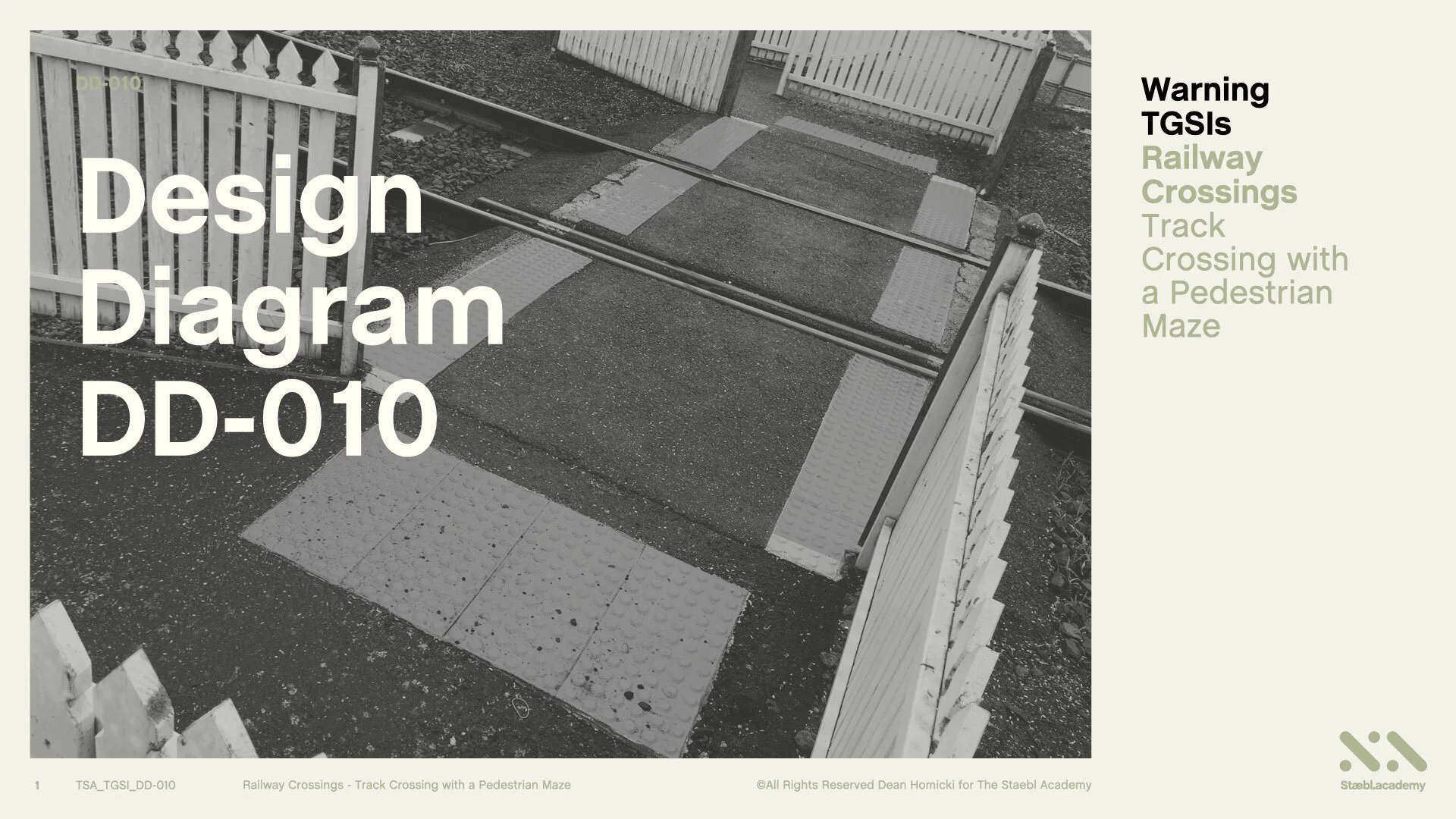
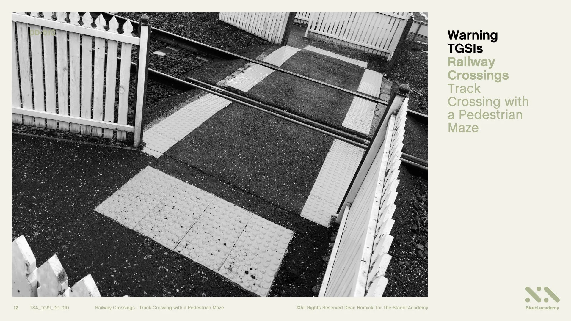
Here is a real-life situation of a Railway Track Crossing and a Pedestrian Maze with Integrated Warning TGSIs installed on the walkway to identify the hazard. The hazard is the Train (Railway) Track.
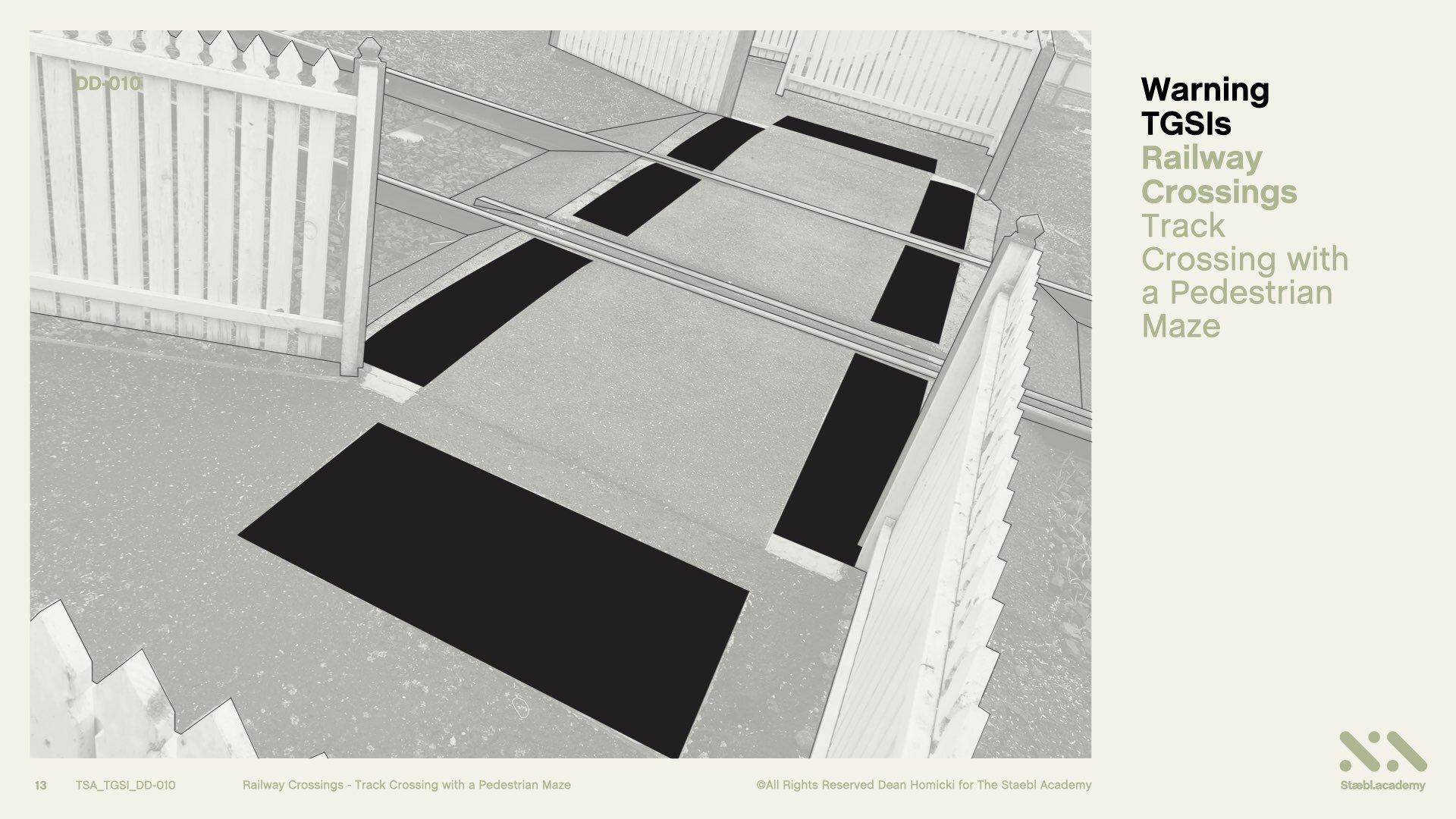
We are going to now convert this image it into a perspective line drawing and view how TGSIs have been used in this application. Here’s the line drawing of the image.
Learning Session
Please note that this course has 2 sections. Section 1 is The Footpath, and, Section 2 is The Footpath Shoulders.
Section One
Let’s begin with Section One
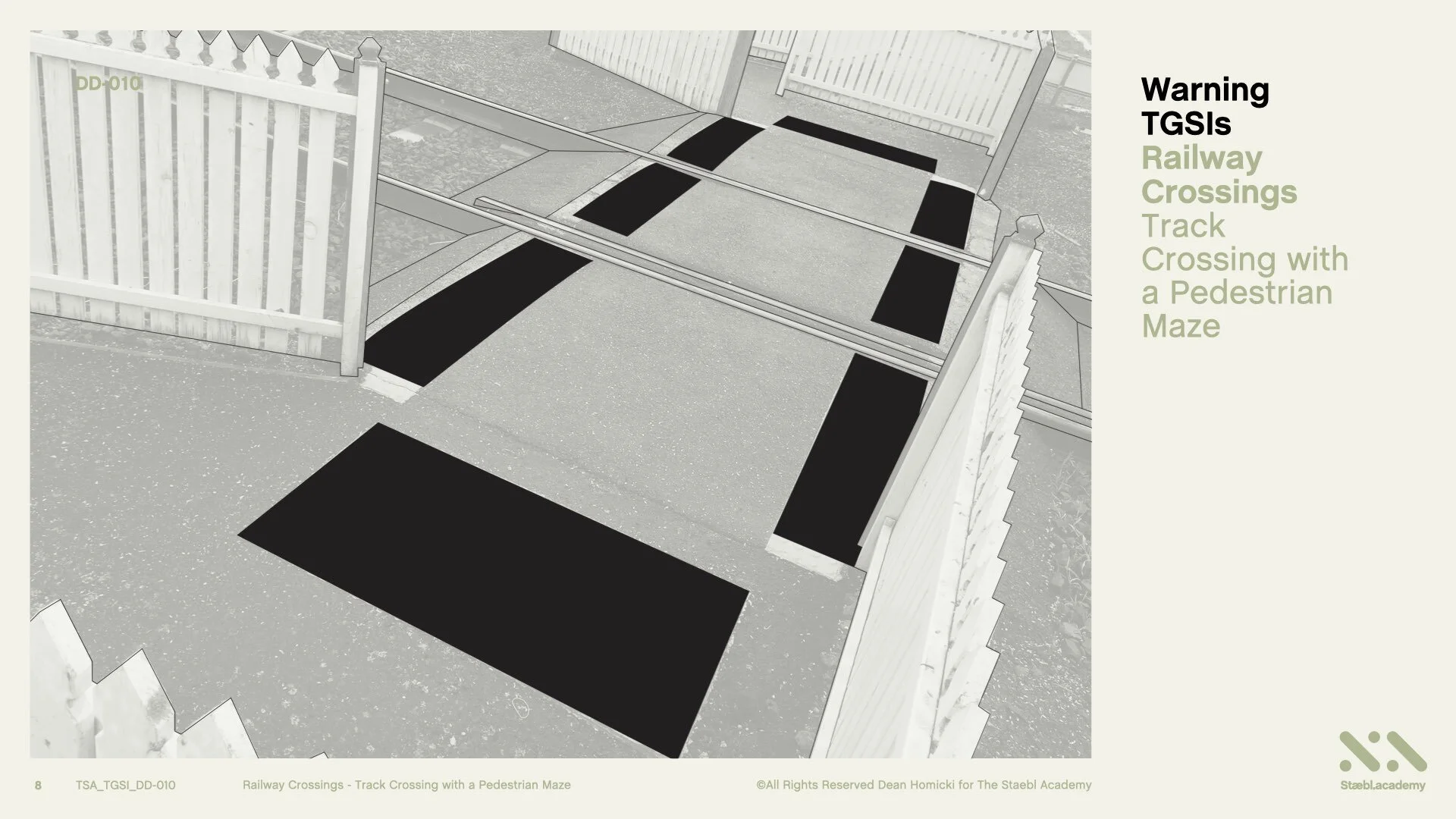
The Footpath: The Pedestrian Footpath across the Railway Tracks.
In this example, people approach this railway track crossing through a Pedestrian Maze. A pedestrian Maze is a physical barrier used to slow pedestrians down and to force them to observe both directions before crossing the railway tracks.
While passing the Maze, a pedestrian is directed to turn to the left and to the right, increasing the probability of seeing an approaching train.
For the orientation of persons who are blind or vision impaired, applying this knowledge enables us to determine how to use TGSIs and conform to the specifications of the Australian TGSI standards.
Let’s Begin
So let’s identify where the Pedestrian Maze or MAZE AREA is located.
Here is the Pedestrian Maze on the far side of Track Crossing. This is a directed or forced approach to the hazard. The hazard is the railway track or the tracks that pedestrians will cross. Here are the Railway Tracks.
And, here on the near side of the Track Crossing is the other Pedestrian Maze. This too is a directed or forced approach to the hazard. We can view here the ‘Accessible Continuous Path of Travel’ across the Railway Tracks.
So, from the beginning the Accessible Path of Travel, or from the threshold of the Pedestrian Maze to the Railway Track Crossing, we require Warning TGSIs to be set back from this edge, 300 mm with a tolerance of +/- 10 mm, for a minimum depth of 600 mm, this equates to 12 TGSI nodes at 50 mm spacings, and, for the full width across the Accessible Path of Travel. These must also be perpendicular to the Direction of Travel.
This applies to the opposite side of the Track Crossing too.
TGSIs must be installed parallel and perpendicular with the TGSIs on the opposite side of the Pedestrian Railway Track Crossing providing for persons who are blind or vision-impaired with safe orientation and travel.
TGSIs for this application also need to conform and perform, with the applicable Slip Resistance and Luminance Contrast Requirements. And here is a real-life TGSI application once more.
Now, TGSIs are also required to be installed on the Footpath Shoulders of the Track Crossing.
Section Two
So let’s continue with Section Two of this design tutorial:
The Footpath Shoulders: The Pedestrian Footpath shoulders on either side of the Track Crossing.
Here’s the Footpath Shoulder on the left. And the Footpath shoulder on the right of the Railway Track Crossing.
On both sides of the Footpath Shoulders, Warning TGSIs are required for a depth of 300 mm. This equates to 6 TGSI nodes at 50 mm spacings. On both sides of the Accessible Path of Travel, TGSIs must be positioned from the perimeter edge and must be perpendicular to the Direction of Travel.
This applies to both sides of the Track Crossing too.
TGSIs must also be (installed) parallel and perpendicular with the TGSIs on the opposite shoulder of the Pedestrian Railway Track Crossing providing for persons who are blind or vision-impaired with safe orientation and travel.
From the beginning of the Accessible Path of Travel, or, from the fence opening of Pedestrian Maze to the Track Crossing, TGSI must also be installed for a minimum length of 1500 mm to the nearest rail, and, inside or, in between the Flangeway Gap.
The Flangeway Gap distance will vary depending on the Track gauge of the Railway. This applies to the opposite side of the Pedestrian Crossing too. TGSIs must also be installed parallel and perpendicular with the TGSIs on the opposite side of the (Footpath) Shoulder and must be perpendicular to the Direction of Travel.
TGSIs for this application also need to conform and perform, with the applicable Slip Resistance and Luminance Contrast Requirements.
And here is a real-life TGSI application once more.
Learning Resources
That’s the conclusion for Warning TGSIs on Railway Crossings: Focusing on Track Crossings with Pedestrian Mazes.
You can also access this course as a concise series of design diagrams in the resource section of our website staebl.academy/design. To access this resource now, click on the link below this video.
Thanks for joining me here at the staebl.academy. I look forward to guiding you through another learning session in the near future. Bye for now.
Listen
Click/Tap the audio player below to listen to the written transcript of this design session as an audible version. This is a streamed broadcast from the Staebl.academy site.
Diagrams
Click/Tap on an image from this learning session to view it as a larger picture. You will then be able to scroll through each individual design diagram in this slide-deck for a closer inspection.


Sources
TSA-TGSI-1.10 - This staebl.academy course module has drawn information from the following sources:
AS/NZS 1428.4.1: 2009 Design for Access and Mobility: Means to assist the orientation of people with a vision impairment - Tactile Ground Surface Indicators - Section 2, 2.2 (a) & (b), 2.3.1 General, 2.3.2, 2.3.3 (a), (b), (e), (f) & (g), Fig 2.1 (a), (b) & (c) AMDT No.2 Dec 2014
AS 1742.7: 2016 Manual of Uniform Traffic Control Devices - Part 7: Railway Crossings - Section 1, 1.1, 1.2, 1.3, 1.4, Section 6, 6.1, 6.2 (a), (b), (c), (d), (e), 6.3, 6.3.1 (ii), 6.3.2, 6.3.3 (a), a (ii), a (iii), (d), Fig 6.1, 6.4, Appendix F, Fig (F1), Fig (F2), Fig (F3), Fig (F4), Fig (F5), Fig (F6) & Fig (F7)
